
The shock absorber damping coefficient is defined as the shocks damping force divided by shaft velocity.
Examining damping performance as a damping coefficient shows details of how the shim stack is tuned, operation of the bleed circuit and shaft velocities where various tuning features of the shim stack kick in.
Learning how to read a damping coefficient curve makes the tuning of shim stacks easier giving more precise control of the shock absorber damping force curve.
Low speed clicker bleed
From zero velocity to the peak of the damping coefficient curve, the shim stack is closed forcing all flow through the bleed system.
The pressure drop and damping force produced by a fixed area orifice bleed system increases with velocity squared.
Dividing velocity squared damping by the shaft velocity makes the damping coefficient increase linearly through the bleed circuit flow range.
Shim ReStackor plots show the open and closed clicker curves indicating the available tuning range of the clicker bleed circuit.
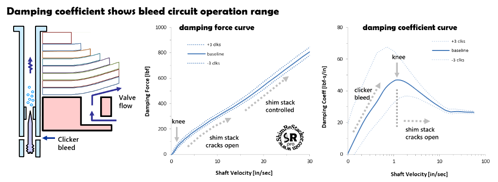
Shim stack cracks open
At the peak of the damping coefficient curve the shim stack cracks open. When the shim stack cracks open the increase in flow area causes the damping coefficient to fall-off. The peak of the curve is often called the “knee” of the damping force curve.
Adding face shims delays opening of the shim stack, moving the “knee” to higher speeds. Crossovers allow the face shims to open earlier moving the “knee” to lower speeds. Simple.
As the shim stack cracks open, the face shims peal back along the sides of the valve port progressively increasing the flow area. The progressive increase in flow area causes the damping coefficient curve to fall-off until the valve port sides are fully open. For the example, that occurs at shaft velocities around 20 in/sec.
A large diameter crossover shim delays opening of the valve port sides stretching out the transition region. A smaller diameter crossover opens more quickly making the drop-off from the "knee" steeper.
Controlling how the shock transitions off of the bleed circuits is something you can definitely “feel” when you ride. That behavior is tuned by hacking around on the crossover configuration and number of face shims.
Detailed tuning of the crossover controlling how the shim stack cracks open is easy to spot on a damping coefficient curve, but nearly impossible on a basic plot of damping force.
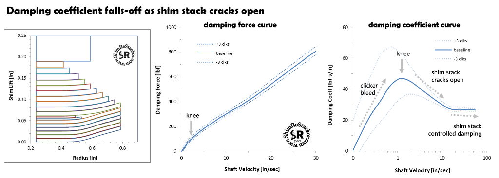
Shim stack cracks open at peak of damping coefficient curve
Shim stack controlled damping
Above 20 in/sec the shim stack is fully open and the stiffness of the shim stack controls the valve port flow area and damping force. The bleed circuits are active but the small flow area has little influence on damping once the shim stack has opened the valve ports. The Shim ReStackor open/closed clicker curves show the small influence of the bleed circuit.
If the damping coefficient curve is sloped downward, as in the example, the damping force is digressive. If the curve is sloped upward, the damping force is progressive. Larger shim stack clamp diameters generally shift the curve from digressive to progressive.
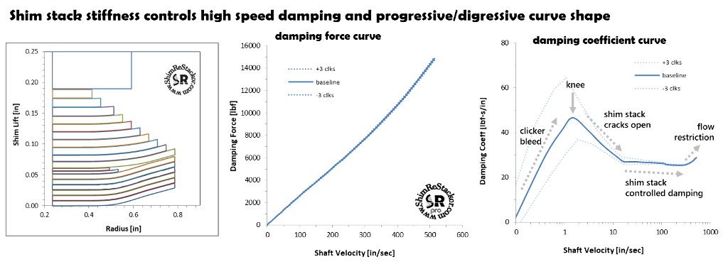
Shim stack stiffness controls damping force above 20 in/sec
High speed flow restrictions
The final feature of the damping coefficient curve is spotting the occurrence of high speed flow restrictions. Flow restrictions at the valve port entrance or port throat cause the damping coefficient curve to kick up at high speed.
For the example, that occurs at velocities around 300 in/sec. The kick up in damping force is easily spotted on the damping coefficient curve, which makes the effect tunable. Spotting the flow restriction on the damping force curve is more difficult.
Damping coefficient tuning
Stepping through the damping coefficient curve, and figuring out the cause of each kink and bend in the curve tells you allot about what is going on inside the shock. Understanding the why makes the kinks and bends tunable, and that gives the capability to reshape the damping force curve to give the features you want.
That same information is all contained in the damping force curve. But spotting the subtle changes in slope as various features in the fluid circuit and shim stack kick in is extremely difficult. The damping coefficient curve highlights those features making them easy to spot and that makes tuning easier and more precise.
Seal drag
Dyno tuners typically subtract seal drag from the measured dyno damping force. Subtracting seal drag highlights the hydraulic damping force of the shock absorber making tuning of bleed circuits and the shim stack easier.
However, seal drag heavily influences low speed suspension motions. Accurate suspension response calculations for small motions around race sag require seal drag to be included in the low speed damping force. Shim ReStackor damping force calculations include seal drag.
At zero velocity seal drag drives the damping coefficient to infinity due to the definition of damping force/shaft velocity.
To interpret low speed damping force on Shim ReStackor damping coefficient plots the seal drag needs to be removed.
The seal drag can be removed by adjusting the “Offset” parameter to force the calculations to produce zero damping force at zero shaft velocity. This is the process dyno tuners use to remove seal drag from dyno data. Shim ReStackor uses the same process (more).
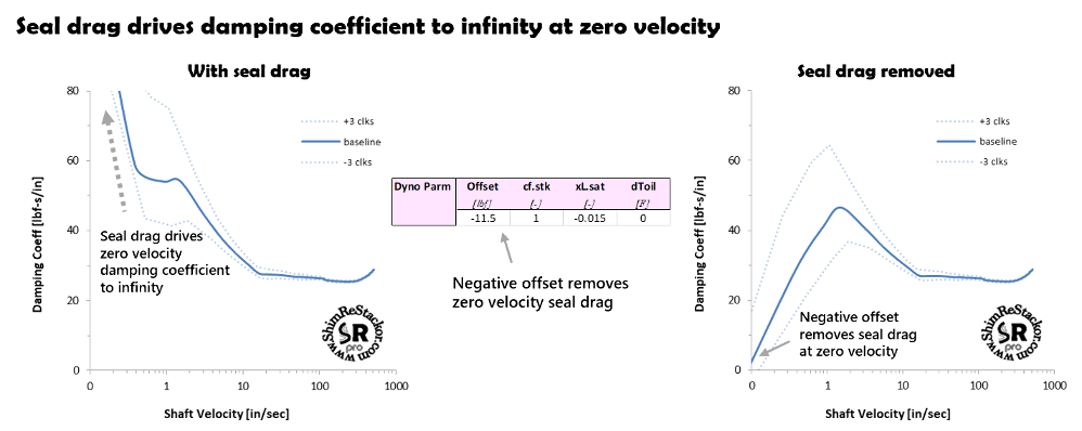
Shim ReStackor damping force offset removes low speed seal drag