- You are here:
-
Home

- Sample apps
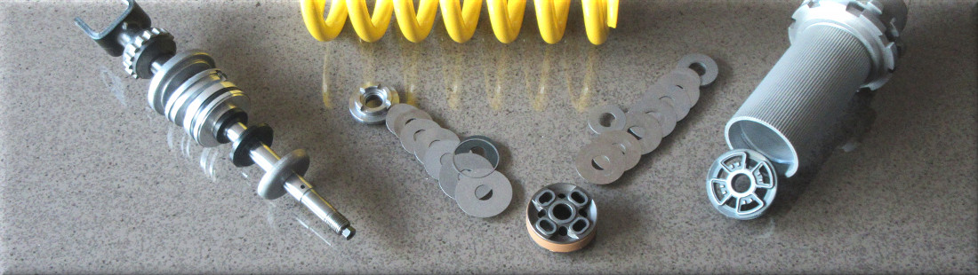
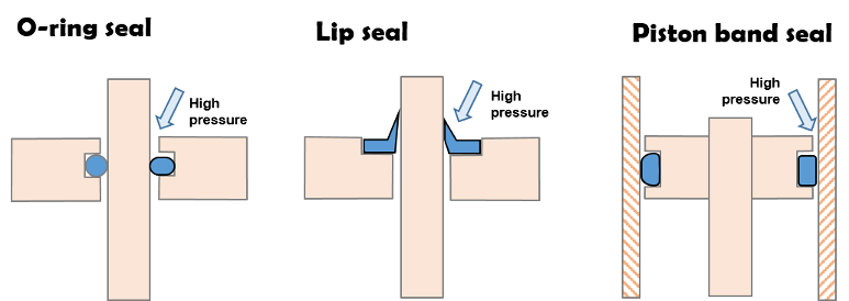
Both O-rings and lip seals are used in shock absorbers. Both seal types are “pressure activated” meaning the sealing force increases as pressure is applied to the seal.
Pressure activated also means the seal drag force increases as pressure is applied to the seal.
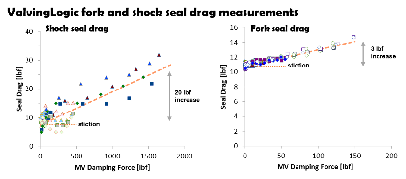
Seal drag data
ValvingLogic has measured seal drag of KYB, Showa and WP shocks under both static and high speed conditions. Shock seal drag increases by 20 lbf at high speed while fork seal drag increases by approximately 3 lbf.
Shim ReStackor damping force calculations include seal drag and the seal drag increase as the shock is pushed to progressively higher pressures at high speed.
There are two components to seal drag:
- Static stiction
- Pressure activated drag
Static stiction causes low speed suspension motions to lockup, preventing the suspension from freely returning to race sag creating poor suspension compliance over small bumps.
Pressure activated drag increases the damping force at high speed due to the increased internal pressure acting on the seal.
Shim ReStackor damping force calculations compute both types of drag and correct for pressure changes due to modification of the shim stack configuration.
Seal drag measurement
Setting race sag gives a direct measurement of seal drag stiction. Lifting the bike slightly and allowing the suspension to settle back to race sag; or pushing the bike down and allowing the suspension to rise to race sag quantifies stiction by the stroke height difference.
The race sag position difference coupled with the suspension spring rate and link ratio quantifies the seal drag stiction force.
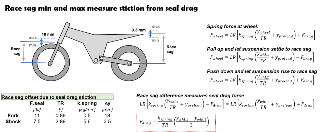
Eleven pounds of fork seal drag produces a race sag difference of 18 mm (+/- 9 mm). Shock seal drag produces a race sag difference of 3.5 mm.
Stiction measurements outside that range indicate the forks may not be aligned, the linkage system needs greasing or the shock has a poorly installed seal causing high drag.
Dyno damping force measurement
Shock absorber damping force measurements are composed of two elements: hydraulic damping from the shock circuits and drag from the shock seals. Dyno tests typically subtract the zero velocity seal stiction from the measured shaft force to highlight the hydraulic damping force produced by the shock.
However, the static stiction dyno correction does not account for pressure activated seals which increase the seal drag by 20 lbf when operated at high pressure as shown by the above ValvingLogic data. That creates a 20 lbf difference between the true hydraulic damping force of the shock and the combined damping plus seal drag measured in dyno testing.
Shock damping coefficient
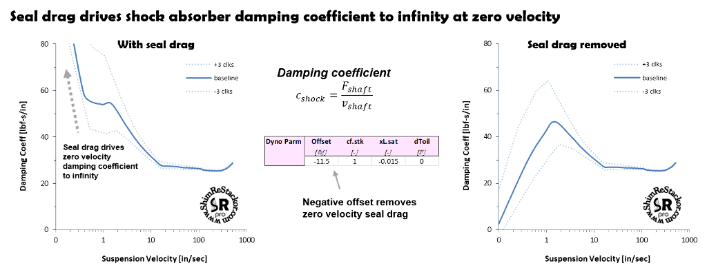
Seal drag dominates the low speed damping force and suspension response for small motions around race sag. Shim ReStackor damping force calculations include seal drag for that reason. The effect of seal drag on low speed damping is easily seen in plots of the shock absorber damping coefficient. As shaft velocities approach zero the damping coefficient goes to infinity due to the definition of damping coefficients as damping force/shaft velocity.
The seal drag force can be removed from Shim ReStackor calculations using the “Offset” input parameter. The Offset input is added to the computed damping force.
Adding a negative offset adjusts the computed damping force to produce zero damping force at zero shaft velocity. This is the same process dyno tests use to correct the measured damping force for seal drag. However, the correction does not correct for dynamic seal drag as mentions above.
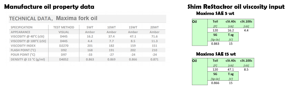
Suspension oils are available in a wide range of viscosities measured in centi-stokes (cSt). Shim ReStackor inputs require the oil viscosity at 40c (cSt.40c) and 100c (cSt.100c), and the oil specific gravity (SG) to define density. Those three parameters define the oil viscosity falloff with temperature (more).
Changing the shock absorber oil viscosity primarily effects damping force at low speed controlled by the clickers and bleed circuits.
Oil viscosity damping
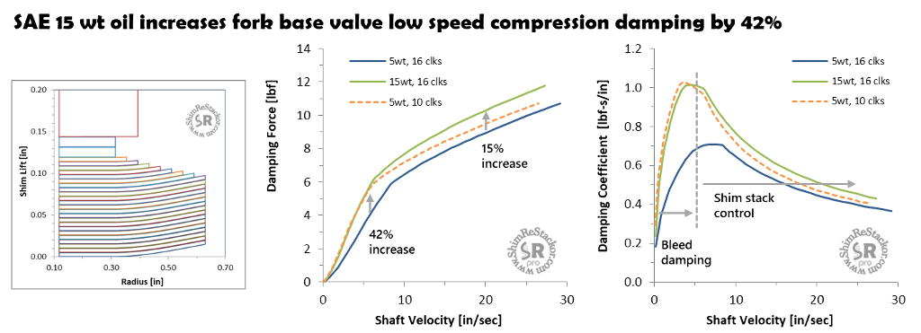
Increasing fork oil viscosity from SAE 5 wt to SAE 15 wt increases the fork base valve low speed compression damping force by 42%. That is equivalent to closing the base valve clickers from a setting of 16 to 10 clicks.
The thicker oil produces higher pressure drops through the bleed circuits forcing the shim stack to crack open earlier. That moves the “knee” of the damping force curve to lower speeds (more).
After the shim stack cracks open at 5 in/sec the damping force increase of the thicker oil is reduced to 15%. Higher pressure drops produced by the thicker oil forces the shim stack to open further partially reducing the effect of the thicker oil.
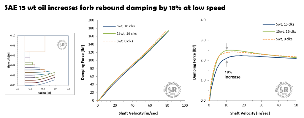
Repeating the above calculations on the fork rebound valve shows an 18% increase in low speed damping using 15 wt oil. The 18% increase is equivalent to running 5 wt oil with the rebound clickers closed.
On the rebound circuit the damping force increase of the thicker oil was less. However, the equivalent clicker change was larger due to the differences in the mid-valve and base valve bleed circuit flow area.
The example illustrates the effect of oil viscosity on damping force is highly dependent on the valve, shim stack and bleed circuit configuration. There is no way to know the effect of thicker oil on damping force without running the specific case of interest.
Oil density
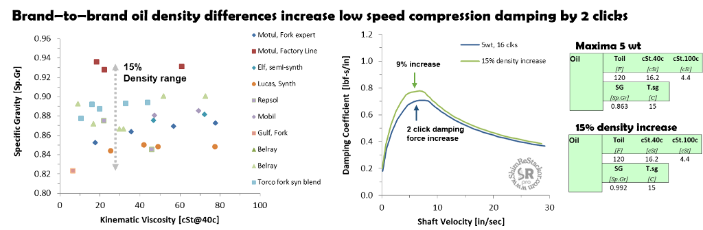
Brand-to-brand differences in oil density range by 15% (more). Higher density oils require higher pressure drops to push the heavier fluid through the shock absorber circuits which increases damping force. Oils with identical viscosities will produce different damping force values due to differences in oil densities.
Running Maxima 5 wt oil with a 15% density increase increases damping force by 9%. That is equivalent to two clicks at 5 in/sec.
An important but little known fact is shock absorber oil contains 10% by volume dissolved gas (nasa). Gas reservoirs pressurized to 147 psi allow nitrogen to slowly diffuse through the bladder, or around the o-ring seals of a piston reservoir, and saturate the oil with dissolved nitrogen after about 4 months.
When expanded back to atmospheric pressure, 10% by volume at 147 psi (10 atm) becomes 100% by volume severely foaming the oil.
Dissolved gas makes the oil in shock absorbers behave like a hot bottle of coca-cola. Keep the cap on and the fluid behaves like a liquid. Crack the cap and the drop in pressure allows the dissolved gas to boil out making the fluid a foamy mess.
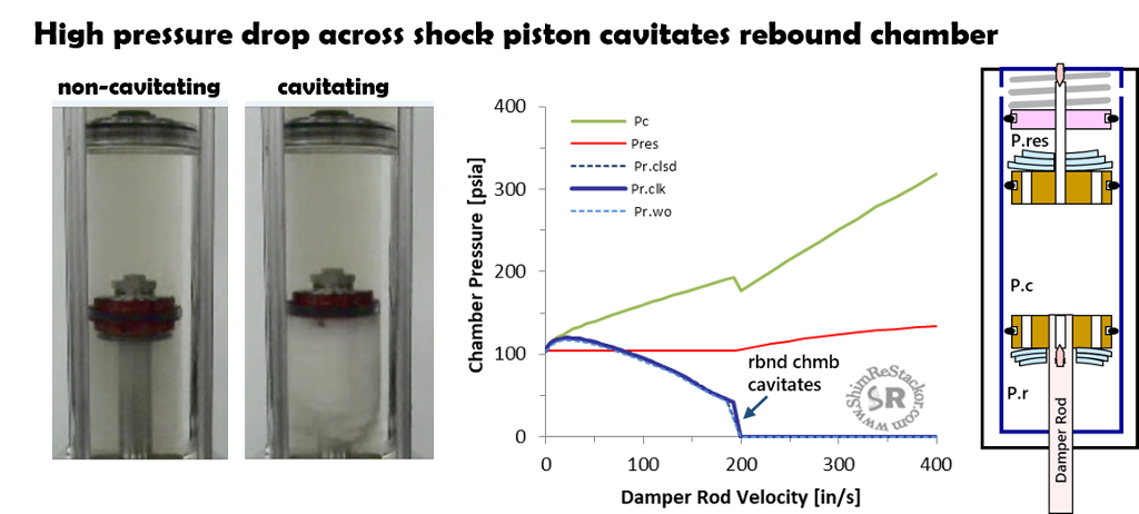
Roehrig made a video to demonstrate the severity of cavitation oil foaming. On the compression stroke the pressure drop across the mid-valve forces pressures in the rebound chamber to drop.
When the rebound chamber pressure drops below the dissolved gas pressure the dissolved gas boils out and foams the oil.
When the shock flips around into the rebound stroke, the piston just wings back through the foamed out oil producing zero rebound damping force. The problem with cavitation isn’t loss of compression damping, it is loss of rebound. That shows up as a squishing noise.
The fix for cavitation is simple. The shock compression adjuster, or fork base valve, needs to backpressure the shock chambers and keep the chambers pressurized, at or above the gas reservoir pressure, across the entire range of shock absorber stroke velocities. Keeping the shock chambers pressurized is equivalent to keeping the cap on a hot bottle of coca-cola.
Tuning shocks to control pressures in the rebound chamber is known as “pressure balancing” the shock. Shim ReStackor makes that easy.
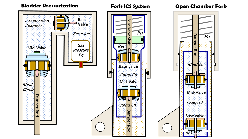
Shock absorber pressure balancing
Shim ReStackor calculations compute the pressure in each chamber of the shock. Pressure balancing simply requires hacking around on the fork base valve shim stack, or compression adjuster on a shock, to keep the rebound chamber pressure (blue line) at or above the gas reservoir pressure (red line).
At zero velocity, the fork ICS system compressed to race sag pressurizes the fork oil reservoir to 100 psi (red line). At low shaft velocities, the rebound chamber pressure initially rises due to back pressure from the fork base valve coupled with float on the mid-valve producing little pressure drop.
As speeds increase to 70 in/sec the pressure drop across the mid-valve matches the back pressure from the base valve forcing the blue and red lines to match at the initial 100 psi oil pressure.
As the fork is pushed beyond 70 in/sec the pressure drop across the mid-valve increases faster than the backpressure from the base valve forcing pressures in the rebound chamber to drop below 100 psi. At that point, gas dissolved in the fork oil will begin to boil out and foam the shock oil.
At 200 in/sec the base valve does not produce enough back pressure to force the required oil flow through the mid-valve. At that point, pressures in the rebound chamber drop to zero forming a vacuum bubble behind the mid-valve and severely foaming the oil in the rebound chamber.
“Pressure balancing” the shock to suppress cavitation oil foaming simply requires hacking around on the fork base valve or compression adjuster shim stack to keep the blue line (rebound chamber pressure) at or above the red line (reservoir pressure) across the shock absorber shaft velocity range.
Pressure balance tuning
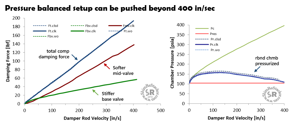
The above example needs more backpressure from the base valve to pressure balance the shock. To get more backpressure, the base valve shim stack clamp diameter and stack taper stiffness was increased. With more damping force from the base valve the mid-valve was softened to keep the overall compression damping force the same.
With the stiffer base valve, the fork can now be pushed to 400 in/sec without cavitating the rebound chamber.
Suppressing cavitation oil foaming allows the shock piston to always move through clean un-foamed oil to give consistent damping performance across the entire range of suspension velocities and stroke frequencies. Suppressing cavitation fixes the hysteresis curves frequently seen shock absorber dyno testing.
Ideally, a pressure balanced shock maintains pressures in the rebound chamber at the initial gas reservoir pressure. Matching the gas reservoir pressure is the minimum requirement to prevent gasses dissolved in the oil from boiling out. Tuning to that minimum requirement also reduces wear on the shaft seals.
However, shock absorbers typically produce rebound damping forces that are double the value of compression. For the above example, the shock produces peak rebound chamber pressures of 500 psi at the maximum rebound stroke velocity and the shaft seals are designed to operate at those pressures.
Suppressing cavitation oil foaming requires tuning the compression valving to maintain pressures in the rebound chamber at or above the initial gas reservoir pressure. The above example exceeds that minimum by 50 psi at velocities around 120 in/sec. The 50 psi overpressure is well within the operating limits of the shock set by peak pressures in the rebound stroke.
Dyno tuning "rules of thumb"
A dyno tuning “rule of thumb” is the compression adjuster should produce about 12% of the overall damping force. Some say that rule is established to give riders required tuning range when adjusting the high speed compression adjuster.
In reality, the 12% “rule of thumb” is a requirement for suppression of cavitation. Stepping through some algebra shows that.
The damping force from the base valve, or compression adjuster in a shock, is equal to the base valve pressure drop times the damper rod area.
The total damping force is the base valve force plus the mid-valve swept area multiplied by the pressure drop across the mid-valve.
On a “pressure balanced” shock the base and mid-valve pressure drops match. The matched pressure drop requirement reduces the equation to the ratio of damper rod to mid-valve diameter squared.
For the special case of a 16 mm damping rod and 46 mm shock piston the 12% “rule of thumb” pressure balances the shock, but only for that specific configuration.
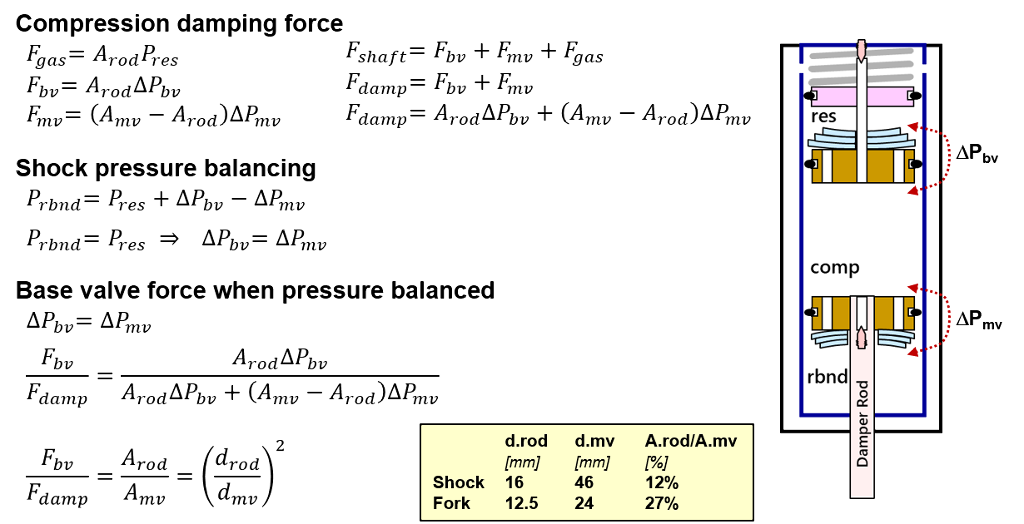
On a fork with a 24 mm mid-valve and a 12.5 mm damper rod a damping force ratio of 27% is required to pressure balance the shock.
The 12% “rule of thumb” works for a shock. But applying that same rule to a fork will severely cavitate the fork chambers. There is no universal rule. The damping force required from the compression adjuster, or fork base valve, changes depending on the damper rod and shock valve diameter.
Shim ReStackor makes pressure balancing the shock easier. The single requirement of pressurizing the rebound chamber at or above the gas chamber pressure suppresses cavitation for all configurations regardless of the damper rod or shock piston diameter. The single rule eliminates the confusion that sometimes tricks dyno tuners into tuning everything to the 12% "rule of thumb" and severly cavitating the shock.
Cavitation and oil foaming control
Pressure balancing shock chambers is a necessary step for tuning forks and shocks to suppress cavitation oil foaming. On a fork, the base valve controls backpressure. On a shock, the compression adjuster controls backpressure. Twin tube shocks replace the compression adjuster with the chamber foot valve.
Regardless of naming conventions, suppressing cavitation requires tuning the shock circuits to keep all of the chambers pressurized at or above the gas reservoir pressure across the entire range of suspension velocities. Direct calculation of chamber pressures in Shim ReStackor makes that process easy.
Damping targets
From test ride results the rider wants to soften low speed compression for small one inch “trail trash” bumps and stiffen high speed for bumps greater than three inches.
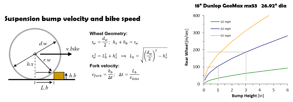
Wheel bump velocity
At a bike speed of 30 mph a one inch bump produces a suspension velocity of 100 in/sec and a three inch bump produces a velocity of 190 in/sec (more).
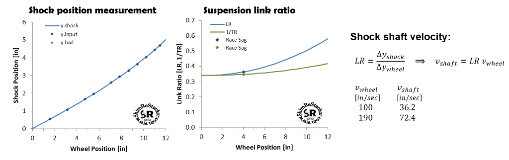
Shock shaft velocity
The suspension link ratio (LR) is computed from measurements of shock shaft and wheel position as the suspension is moved through the stroke. Link ratio specifies the ratio of shock shaft to wheel bump velocity.
For the example where a wheel bump speed of 100 in/sec produces a shock shaft velocity of 36.2 in/sec and the three inch bump velocity of 190 in/sec produces a shock shaft speed of 72.4 in/sec.
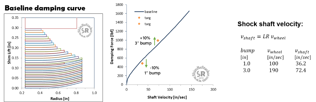
Damping tuning targets
From the test ride results, the rider wants to soften low speed compression damping by 10% over small one inch bumps and stiffen compression damping by 10% on bumps larger than three inches.
Running Shim ReStackor on the current setup gives the damping force curve and the two damping targets for the new setup.
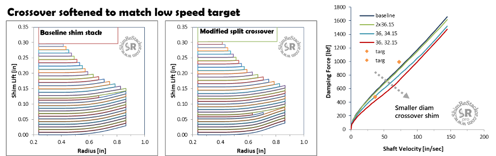
Low speed damping
The baseline shim stack has a crossover. To soften low speed damping the shim stack needs a larger crossover gap and a stiffer high speed stack to hit the +10% target on three inch bumps.
To figure out the crossover needed a series of calculations were run using progressively smaller crossover shim diameters. A split crossover using a 36.15 and 32.15 shims is close to the low speed damping target.
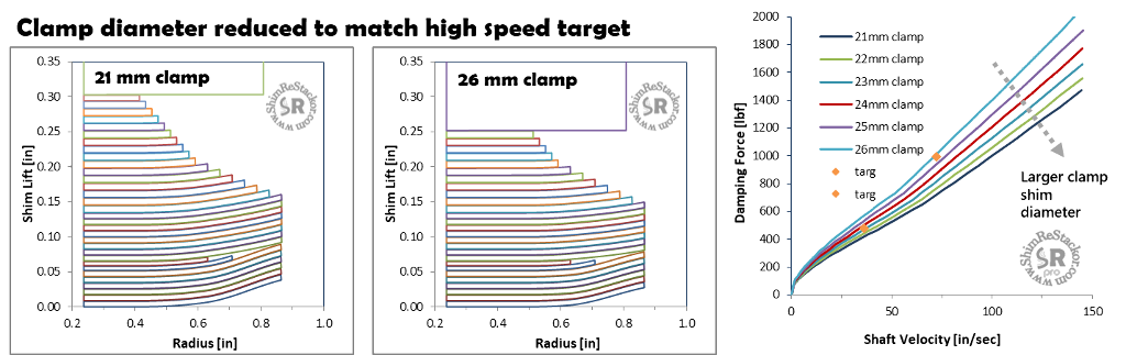
High speed damping
Hitting the 10% increase in high speed damping requires a stiffer high speed stack. A series of calculations were run using progressively larger stack clamp diameters.
A 26 mm stack clamp comes closest to hitting the high speed three inch bump target. With the stiffer high speed stack the crossover needs to be readjusted to stay on the low speed damping target.
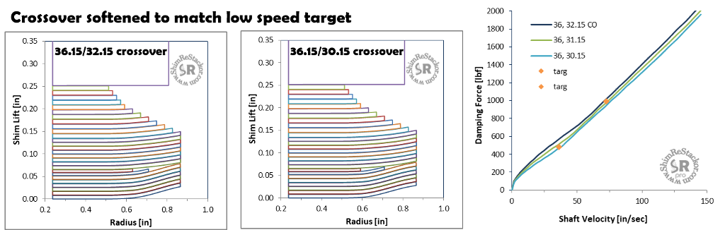
Crossover adjustment
The low speed one inch bump damping target is in between a 30.15 and 31.15 crossover shim.
Using the smaller 30.15 mm crossover and adding a face shim hits both the low and high speed damping targets.
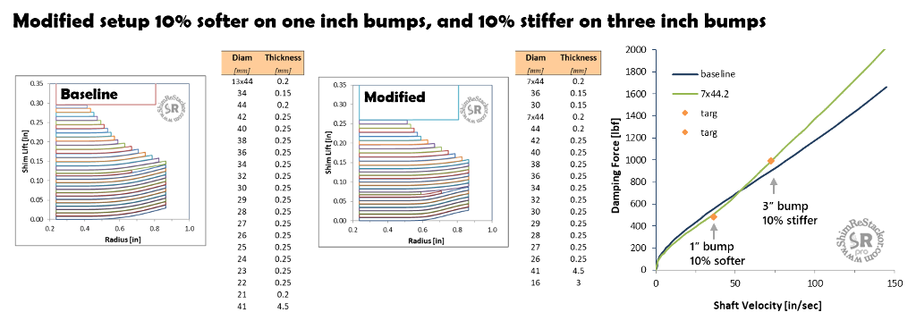
Reshaping damping force curves
There is no secret formula to determine the shim stack modifications needed to hit a specific damping force target. Tuning is simply done through hacking.
For this example: The crossover was tuned to hit the low speed one inch bump damping target. Then the high speed stack was tuned to hit the high speed damping target on three inch bumps.
The interactive crossover used in the configuration coupled with the stiffer high speed stack caused low speed damping to increase with the stiffer high speed stack.
A couple more modifications to the crossover and added face shim hit both the low and high speed targets. In total, 12 runs where needed to reshape the damping force curve.
On a dyno at $50/stroke the modification would cost $600.
In total, 12 runs where needed to reshape the damping force curve and hit the tuning targets.
There are two ways to stop a suspension from bottoming:
- Stiff springs with soft damping
- Soft springs with stiff damping
What is the difference in suspension performance?
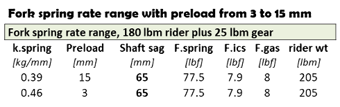
Fork spring rate range
A 180 lbm rider (with 25 lbm gear= 205 lbm) can run fork spring rates from 0.39 to 0.46 kg/mm and hit race sag at 65 mm, measured on the stanchion tube, by changing the fork spring preload from 15 to 3 mm (more).
What is the difference in suspension performance between running a stiff or soft spring?
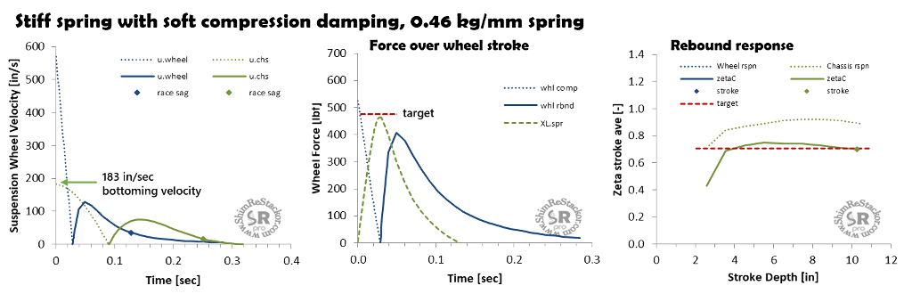
Stiff spring setup
Compression damping on the stiff 0.46 kg/mm spring was set to match the peak spring force on a ten inch wheel bottoming stroke. Matched peak force gives a plush bottoming stroke. Jjump landings bottom at an impact velocity of 183 in/sec with the stiff spring, equivalent to a 3.6 ft jump height (more).
Rebound damping was set at zeta 0.7 and tuned to give a flat zeta response across the range of stroke depths (more).
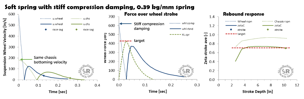
Soft spring setup
The softer 0.39 kg/mm spring needs a 15% increase in compression damping to produce the same 183 in/sec jump landing bottoming resistance. On a 10 inch wheel bottoming stroke, the stiffer compression damping produces a 180 lbf increase in damping force at bump impact.
Stiff compression damping at bump impact makes the suspension “feel” harsh.
Rebound damping was tuned to match the softer spring and produce the same zeta 0.7 rebound response across the range of stroke depths.
Soft versus stiff spring suspension performance
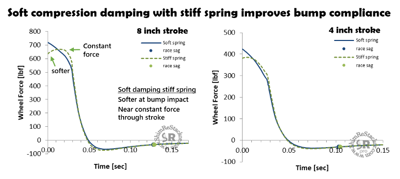
The plots below show the suspension force acting on the wheel through the suspension stroke. “Wheel Force” is the sum of spring plus damping force.
Hitting a bump hard enough to bottom the wheels requires a bump velocity of 600 in/sec for both setups. The stiff spring setup produces a peak compression damping force approximately equal to the peak spring force. Matched peak force produces a near constant force through the compression stroke (green line) giving the suspension a consistent “feel”.
The soft spring case (blue line) requires stiffer compression damping to match jump landing bottoming resistance. The stiffer compression damping produces a higher force at bump impact followed by a falloff to the peak spring force at bottoming. On an eight inch wheel bottoming stroke the soft spring/stiff compression damping setup produces a 100 lbf stiffer force at bump impact making the suspension “feel” harsh.
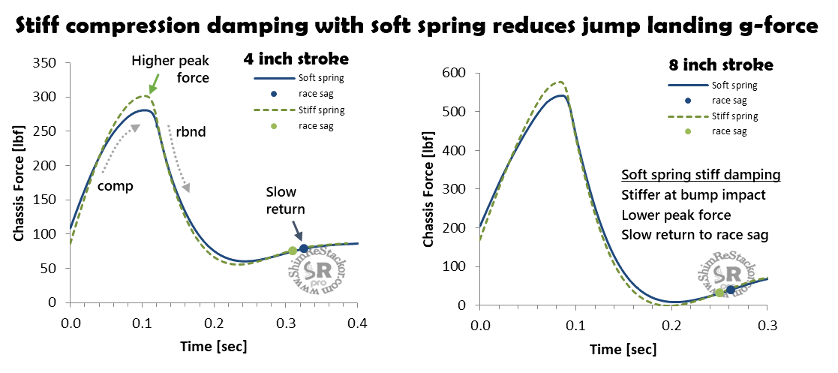
Jump landings
On jump landings, the soft spring with stiff compression damping absorbs more of the ground impact early in the stroke. The soft spring produces less force at the end of stroke reducing the g-force on the rider at bottoming. The soft spring case is plusher on jump landings.
On rebound, the soft spring takes more time to return to race sag making the setup susceptible to packing.
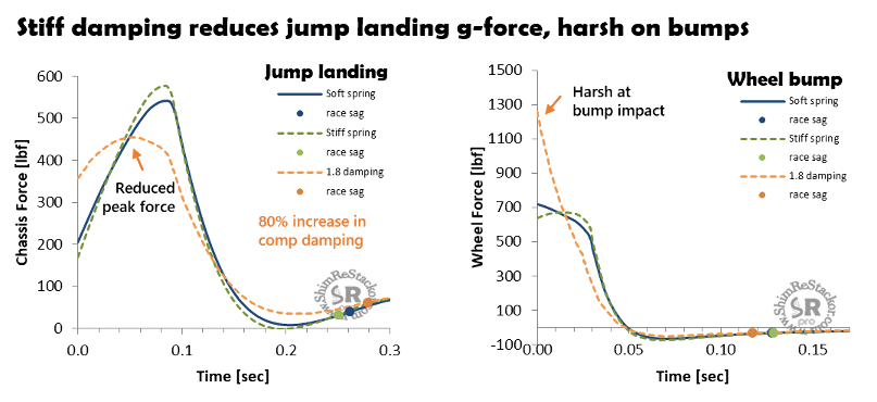
Increasing compression damping by 80% further demonstrates the effect of compression damping on jump landings. Stiff compression damping absorbs the jump landing impact early in the stroke allowing the use of softer springs, which reduces the peak spring force at end of stroke.
Reducing the end of stroke spring force reduces the g-force on the rider making the soft spring case plusher on jump landings.
However, stiff compression damping produces higher forces at bump impact. The 80% increase in compression damping generates a bump impact force of 1250 lbf forcing the chassis to deflect off the bump.
Stiff compression damping reduces the rider jump landing g-force but gives poor suspension compliance on braking bumps or root and rock impacts.
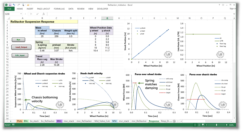
Shim ReStackor suspension response
Suspension response calculations combine damping force, spring and gas force, and rider weight to determine wheel and chassis bottoming velocities and the forces acting on the wheel through the suspension stroke.
A simple plot of spring and damping force acting on the wheel through the suspension stroke gives some insight into suspension “feel” and features of various tuning options.
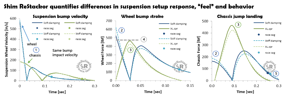
Stiff spring with soft comp damping
- Same wheel and chassis bottoming velocity
- Softer bump impact force improves suspension compliance
- Stiffer spring force at bottoming increases g-force on rider
- Matched peak force produces a constant force through the stroke giving the suspension a consistent “feel”
- Faster return to race sag reduces packing
The reduced bump impact force and faster return to race sag makes the stiff spring with soft compression damping the better setup for rocks and braking bumps.
Soft spring with stiff comp damping
- Same wheel and chassis bottoming velocity
- Higher force at bump impact makes the setup harsh
- Softer spring force at bottoming reduces jump landing g-force on rider
- Peak force (2) higher than spring force (3) causes chassis to deflect off bumps
- Slow return to race sag increases rebound packing
The reduced rider g-force on jump landings makes the soft spring with stiff compression damping the better setup of MX jump landings, but compromises compliance on braking bump.
Shim ReStackor numerical test bed
Shim ReStackor response calculations provide a numerical test bed for comparison of various tuning options. A simple plot of spring and damping force acting on the wheel through the suspension stroke gives insight into the suspension “feel” and the effect of various tuning options. Understanding those differences allows smart tuning decisions separating the effect of spring rate and damping on suspension “feel” and performance.
Calculations include the effect of compression adjusters, fork base valves, shim stack float, crossovers, spring rate and gas force allowing balancing of the system over the entire range of stroke depths and suspension velocities.